TrueView 660
£142,618.18 excl. VAT
Advanced LiDAR Technology
Dual Drone and Mobile Mapping Capability
Triple Calibrated Mapping Cameras
Survey Grade Sensor
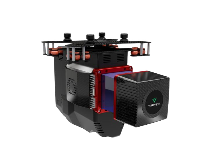
The TrueView® 660 is GeoCue’s third generation RIEGL integration built with the
miniVUX-3UAV and triple mapping cameras (right, left, nadir) for high accuracy
mapping with excellent vegetation penetration and wire detection in a lightweight payload package. In addition, you can upgrade to high-resolution Sony
RX1R2 or Sony a7r imaging camera for even higher performance.
High-Accuracy RIEGL Sensor
Built with the miniVUX-3UAV, the TrueView 660 offers a 300 kHz pulse rate at a 120° LiDAR FOV. It provides 15 mm accuracy and typical 10 mm precision, making it ideal for the most demanding engineering-grade surveys.
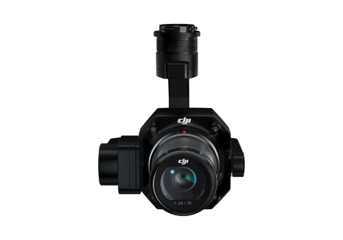
Triple Camera Colorization
The system features three mapping cameras (right, left, and nadir) that provide true colorization over a 113° FOV. The calibrated Sony mechanical leaf shutters minimize motion blur for crystal-clear results.
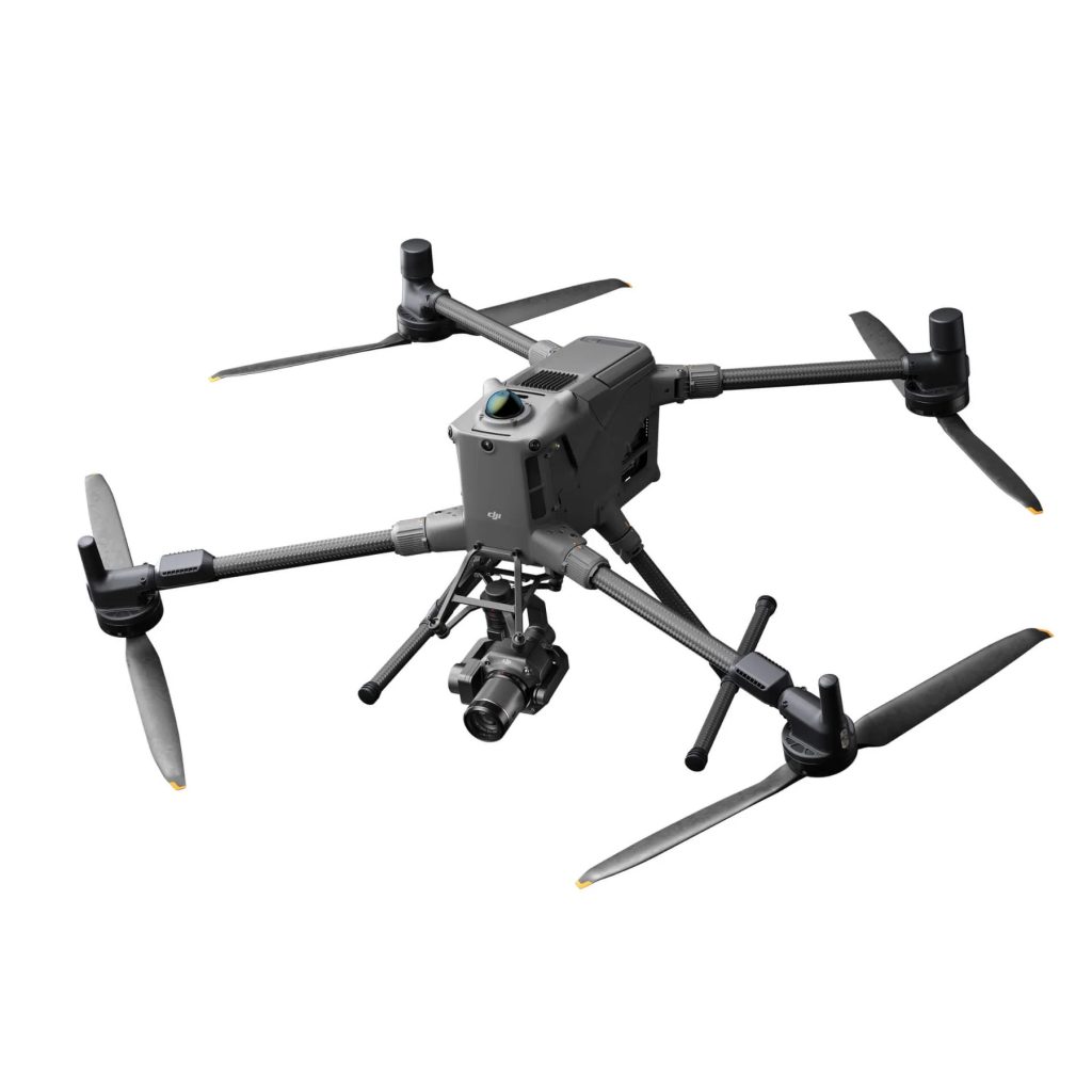
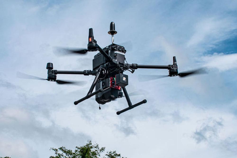
Dual Drone & Mobile Capability
This system is uniquely flexible, offering optional mobile mapping capability alongside its standard UAV configuration. Its lightweight 2.6 kg payload ensures compatibility with a wide range of drone brands, including DJI, Freefly, and Skyfront.
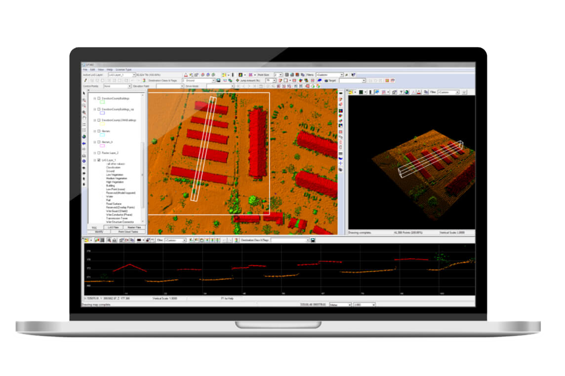
Powered by LP360 Drone
The TrueView 660 comes fully integrated with LP360 Drone, including professional processing modules like Strip Align, 3D Accuracy, and Photo. This allows users to post-process raw flight data into colorized, georeferenced 3D LiDAR point clouds and high-accuracy orthomosaics within a single, simplified workflow.
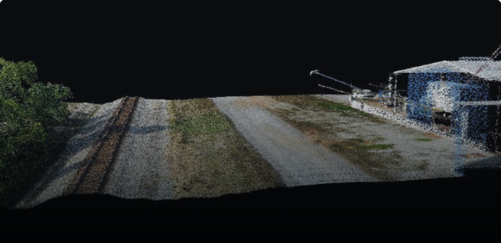
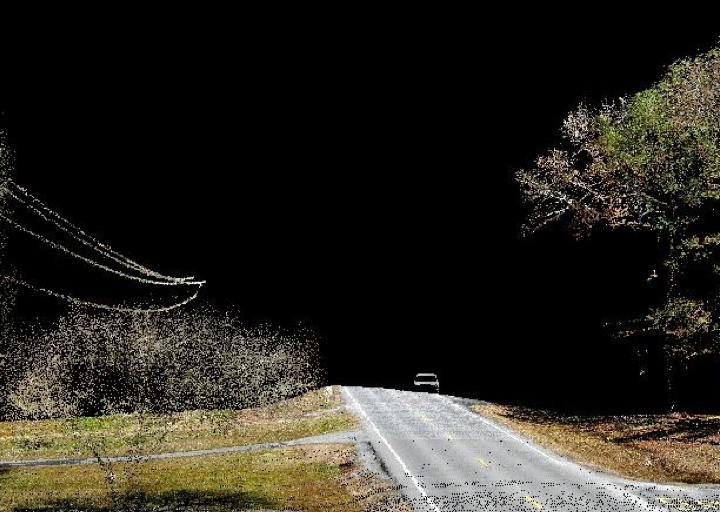
Precision for Critical Infrastructure
With its excellent vegetation penetration and superior wire detection capabilities, the TrueView 660 is optimized for Rail Inspection, Powerline Wire Extraction, and Road Design. It is NDAA-compliant, ensuring it meets the security requirements of high-level government and enterprise projects.
Featured Applications
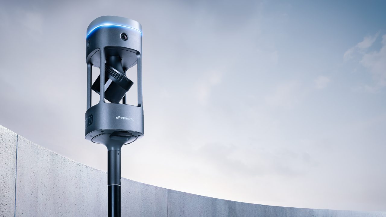
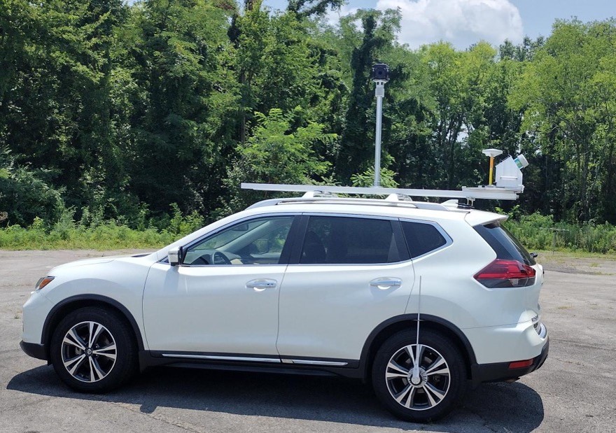
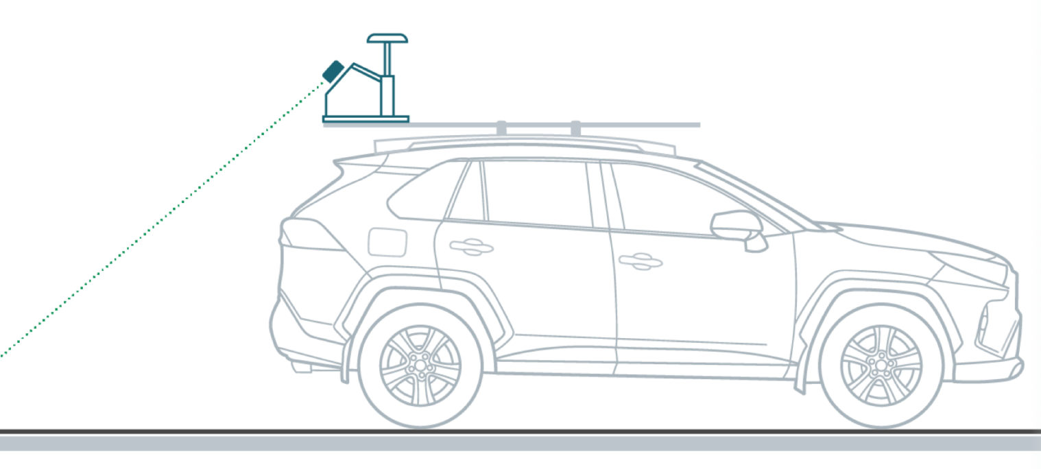
Flexible field operation with optional mobile vehicle mounting
In complex project environments, there are times when drone flights aren’t possible—such as in dense, high-population areas or restricted zones. In these cases, the sensor can be deployed in mobile mapping mode.
For projects requiring multiple viewpoints and enhanced detail, combine both drone and mobile LiDAR modes. This hybrid approach delivers comprehensive coverage—the best of both worlds—to accurately recreate your environment.
Specifications
| Specification | Value |
|---|---|
| Data Collection | LiDAR + Imagery |
| LiDAR Scanner | RIEGL miniVUX-3UAV |
| LiDAR Beams/Returns | Up to 5 per outgoing pulse |
| LiDAR Range - usable | 100 m for targets with > 20% reflectivity |
| Positioning and Orientation System | (660) Applanix APX-20 |
| Pulse Repetition Rate | Up to 300 kHz (selectable)* |
| Scanner Performance |
|
| GNSS/INS Performance |
660
|
| System Performance |
|
| Camera Sensor | 3 Sony IMX-183: 1”, 20 MP, RGB -> 60 MP per payload ***Optional upgrade to high-resolution Sony RX1R2 or Sony a7r. Ask your salesperson for details. |
| Mass | (660) 2.6 kg (IMU-90) or 2.8 kg (IMU-82) (with standard 3 camera package) (payload unit only - no accessories including battery, mount, antenna, power adapter) |
What's included
Accessories Parts
TrueView 660 LiDAR Sensor Payload
USB Thumbdrive
GNSS Antenna
Sensor Hardcase
Concentric Target
Software/Data Management
LP360 Drone Processing Software
Includes Strip Align and Photo Add Ons
Support
1 year of hardware and software support
Drone Platforms
The TrueView 3D Imaging Sensors are designed as a lightweight payload, offering flexible integration with a wide range of drone platforms. Geocue has worked with several drone manufacturers to help provide customers with a complete drone mapping solution. If your preferred brand isn't listed, get in touch with our team to discuss custom integration options!

Buy TrueView 660
FAQs
TrueView 3D imaging Sensors are designed and manufactured in our Huntsville, Alabama, USA facilities.
Data from a standard LIDAR system can be used to generate a 3D monochromatic point cloud. Attributes of the point cloud typically include: • X, Y, Z position in an exploitation spatial reference system (SRS) • High resolution GPS time of pulse • Intensity of the laser return • Return number (if your LIDAR is multiple return capable) • Scan angle (angle of the beam relative to nadir when this point was detected) • Flight line (swath) ID
Derived products are what the name implies – analytic data derived from the base TrueView 655/660 products. These are generated using workflows and tools within LP360 Drone. Examples of derived products include: • Classified ground model – 3D LIDAR points that represent bare earth. These are generated using both automatic and manual editing tools in LP360 Drone • Automatically derived planar surfaces such as building roof prints • Topographic contours • Automatic and manual digitized stockpile boundaries (“toes”) • Volumetric analysis such as stockpile volumes and cut/fill computations • Profiles and cross sections • Automatic rail extraction tools (classified rail points, vectorized center line) • Automatic power line extraction tools (classified wire points, vectorized catenaries) • Gridded elevation models derived from ground points and first surface points In addition to the above, LP360 Drone supports feature-constrained (“breakline enforced”) modeling. This allows creation of surface data that is constrained by features such as water body boundaries, edge of pavement, downstream flow, retaining walls and so forth.